

MIG welding carries a reputation for being the “easy” process, the one you hand to a new hire and expect production runs by Friday. That assumption costs shops real money. In industrial fabrication, where structural integrity, cycle time, and rework rates all hit the bottom line, MIG welding demands the same level of process discipline as any advanced joining method. This article breaks down the real mechanics behind the process: the transfer modes that drive arc behavior, the parameter relationships that define bead quality, and the defect patterns that derail production. Whether you run a high-volume fab shop or manage a mixed-process floor, this is the depth your team needs.
Table of Contents
- Understanding MIG welding: The basics and beyond
- The four metal transfer modes: Choosing the right arc for your job
- Fine-tuning your MIG welds: Parameter adjustments and process control
- Common industrial MIG welding defects and how to fix them
- What most MIG welding guides miss: Real-world process integration
- Upgrade your MIG results with industry-leading welding supplies
- Frequently asked questions
Key Takeaways
| Point | Details |
|---|---|
| MIG welding is advanced | Industrial MIG welding demands technical knowledge and precise process control for best results. |
| Transfer mode matters | Choosing the right metal transfer mode directly affects weld quality, speed, and cost efficiency. |
| Parameter tuning prevents defects | Fine-tuning voltage, wire feed, and technique minimizes common flaws and rework in industrial settings. |
| Holistic approach wins | Top-performing shops integrate welding expertise with process improvement for maximum productivity and consistency. |
Understanding MIG welding: The basics and beyond
MIG welding, short for Metal Inert Gas welding, is formally classified as Gas Metal Arc Welding (GMAW) by the American Welding Society. The process uses a continuously fed consumable wire electrode, a shielding gas supply, and a DC power source to create an electric arc between the wire and the base metal. That arc melts both the wire and the workpiece, forming the weld pool.
The four primary components you need to keep dialed in are the power source, wire feeder, gas supply, and welding torch. Each one influences arc stability and bead quality. A wire feeder running inconsistently, even by a fraction, produces irregular deposition and variable penetration. The gas supply protects the molten pool from atmospheric contamination, so flow rate and mixture directly affect porosity risk and bead appearance.
For industrial fabrication shops, MIG (GMAW) holds real advantages over stick (SMAW) and TIG (GTAW):
- High deposition rates that allow production runs at speeds stick simply cannot match
- Easy adaptation to automation through robotic arms and semi-automatic setups
- Versatility across metals including mild steel, stainless, and aluminum with wire and gas changes
- Lower post-weld cleanup when parameters are tuned correctly, reducing finishing labor
- All-position capability in short-circuit mode without fixturing adjustments
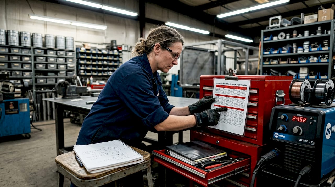
Understanding your MIG welder setup basics from day one prevents the trial-and-error that bleeds production time. Pro Tip: Industrial applications require precise parameter control for consistent results. Even with Auto-Set machines, always validate settings against your actual material thickness and joint configuration before running production parts.
One of the most critical yet underappreciated aspects of MIG welding is that the four metal transfer modes operate under fundamentally different physics. Short-circuit transfer runs at 16 to 22 volts with low heat, suits thin materials and all positions, but produces higher spatter. Globular transfer at 22 to 26 volts creates irregular drops and even more spatter. Spray transfer above 26 volts delivers fine droplets, deep penetration, and high deposition but is limited to flat and horizontal positions. Pulsed transfer uses alternating current peaks to replicate spray-like quality while remaining usable in all positions. Each mode is a different tool, and using the wrong one for the job is like grinding with a flap disc when you need a cutoff wheel.
The four metal transfer modes: Choosing the right arc for your job
Once you understand the system, the next discipline is selecting the right arc behavior for the material, joint, and position in front of you. Mode selection is not a preference. It is a calculated decision that drives speed, quality, and rework rates across every shift.
Here is a direct comparison of all four modes:
| Transfer mode | Voltage range | Best use case | Key advantage | Common pitfall |
|---|---|---|---|---|
| Short-circuit | 16 to 22V | Thin sheet, all positions | Low heat input, versatile | High spatter, fusion issues on thick plate |
| Globular | 22 to 26V | General steel, flat only | Transition zone, higher deposition | Irregular drops, very high spatter |
| Spray | 26V and above | Thick flat/horizontal production | Deep penetration, deposition up to 25 lb/hr | No out-of-position use |
| Pulsed | Varies by machine | Aluminum, stainless, all positions | Low heat, spray-like quality anywhere | Higher equipment cost, complex setup |
The production data on these modes is compelling. Spray and pulsed transfer achieve deposition rates between 6 and 25 lb/hr with smooth bead profiles, making them the go-to choices for thick flat production work. Short-circuit suits industrial thin sheet and positional work due to its versatility and low heat but carries the penalty of higher spatter and potential cold-lap if voltage dips too low. Pulsed mode specifically reduces heat input by 30 to 50 percent compared to spray transfer, making it the standard for aluminum and stainless steel applications where distortion and burn-through are constant risks.
Industry insight: Pulsed MIG has largely replaced conventional spray transfer in high-volume aluminum and stainless fabrication because it delivers spray-quality fusion without the positional restrictions. Shops that still run conventional spray on stainless are leaving productivity and quality gains on the table.
When evaluating how mode selection impacts your floor, consider these factors:
- Spatter rate directly affects cleanup labor and anti-spatter consumable costs
- Travel speed in spray mode can be two to three times faster than short-circuit on the same joint
- Rework rates spike when operators use short-circuit on thick material and get incomplete fusion
- Shielding gas must match the mode: C25 (75/25 argon/CO2) for short-circuit, pure argon or argon/helium blends for spray and pulsed on aluminum
Shops running multiprocess welding options can switch between modes efficiently without investing in separate dedicated units, which matters when your production mix changes weekly. Improving production efficiency at the arc level compounds across every job, especially in contract fabrication environments where margins are thin.
Fine-tuning your MIG welds: Parameter adjustments and process control
Transfer mode gives you the framework. Parameter control gives you the result. The three variables you adjust most often are voltage, wire feed speed (WFS), and contact tip to work distance (CTWD), which most welders call stickout.
Voltage controls arc length and bead width. Higher voltage widens the bead and flattens the crown. Lower voltage tightens the arc and builds a more convex bead. Wire feed speed controls amperage and heat input. Faster WFS drives more current, which increases penetration and deposition. CTWD affects both: longer stickout increases resistance heating in the wire, effectively raising the melt-off rate without changing the arc energy. In practice, stickout inconsistency is one of the most common sources of variable penetration on production parts.
Follow this sequence when dialing in parameters for a new job:
- Set voltage and WFS to the manufacturer baseline for your wire diameter and material thickness.
- Run a test pass and evaluate the sound. A healthy short-circuit arc produces a consistent crackling sound, often described as “bacon sizzle.” Erratic popping signals voltage is too low or WFS is too high for the arc.
- Inspect the bead profile. A flat, slightly convex bead with smooth toes indicates correct parameters. A tall, narrow bead means low voltage. A flat, wide bead with undercut suggests voltage is too high.
- Adjust voltage in 0.5V increments rather than large jumps. Small changes isolate the variable you are correcting.
- Check stickout. For most solid wire MIG, 3/8 to 5/8 inch is the standard. Verify your operator is maintaining it consistently throughout the run.
- Cross-reference travel speed. Slow travel creates excessive buildup and potential burn-through on thin material. Fast travel causes undercut and reduced fusion.
The tuning principles behind sound and bead shape are not secondary skills. Experienced welders use them as real-time diagnostics without stopping the arc. Voltage adjustments directly control arc length, and WFS adjustments directly control amperage and heat input. Porosity points to dirty base metal or inadequate shielding gas coverage. Undercut signals travel speed is too fast for the current heat input. Lack of fusion usually means heat is too low or stickout is too long, putting the wire too far from the arc’s effective penetration zone.
Pro Tip: Before making major parameter overhauls when a defect appears, try one variable at a time and document the result. Shops that keep parameter logs for each material and joint configuration cut their setup time on repeat jobs by 40 to 60 percent. Access strong voltage and wire feed advice and apply the same discipline to your MIG parameter control on every new setup. Resources on process improvement for welding reinforce that systematic parameter documentation is one of the highest-ROI habits a shop can build.
Common industrial MIG welding defects and how to fix them
Every fabrication shop encounters defects. The difference between an average shop and a high-performance operation is how fast they identify root cause and close the loop before the problem runs across multiple parts.
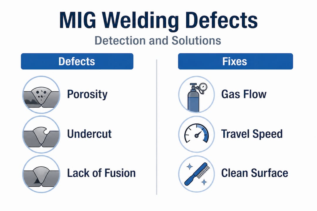
The three defects you will encounter most in industrial MIG work are porosity, undercut, and lack of fusion.
| Defect | Primary cause | Diagnostic cue | Industrial consequence | Proven remedy |
|---|---|---|---|---|
| Porosity | Dirty base metal, low gas flow, moisture in wire | Pits or voids on bead surface or cross-section | Failed NDT inspection, structural weakness | Clean metal to bare, verify gas flow at 25 to 35 CFH, check wire storage |
| Undercut | Travel speed too fast, voltage too high | Groove along the bead toe on base metal | Stress concentration, crack initiation under load | Reduce travel speed, lower voltage, adjust work angle |
| Lack of fusion | Low heat, long stickout, improper joint prep | Cold-lap appearance, bead sits on surface not fused | Critical structural failure risk, automatic reject | Increase WFS, reduce stickout, improve joint fitup |
The root causes of these defects connect directly back to parameter choices. Porosity from dirty metal is a prep issue. Porosity from low gas coverage is a setup issue. Both are preventable before the arc ever starts. Undercut and lack of fusion are both correctable through parameter discipline, not more expensive consumables or equipment.
Preventative steps that reduce defect occurrence during setup and production:
- Clean base metal with acetone or wire brush before welding, especially on aluminum and galvanized steel
- Verify gas flow rate at the start of every shift, not just once per day
- Inspect contact tips regularly; worn tips cause erratic arc behavior and inconsistent stickout
- Check wire spool condition for moisture or surface oxidation, particularly after weekends or storage periods
- Validate fitup and gap before running production; excessive root gap on thin material invites burn-through, tight fitup on thick plate can cause LOF
Taking steps to minimize rework costs through preventative defect control pays dividends that dwarf the time invested in pre-run checks. A single structural weld rejected at final inspection can cost more in rework, delay, and customer impact than an entire week of careful setup discipline.
What most MIG welding guides miss: Real-world process integration
Here is the honest perspective after working with fabrication shops across a range of production environments. The gap between a welder who makes beautiful beads and a shop that runs consistently profitable production is not technique. It is integration.
Most guides teach defect identification and parameter adjustment in isolation, as if each weld exists in a vacuum. The reality is that individual weld quality is only one node in a chain that includes material handling, joint prep, fixture consistency, gas supply logistics, and operator rotation. A perfectly dialed-in MIG setup degrades instantly when a new wire spool comes from a different lot, when a gas cylinder runs low mid-shift, or when an operator substitute changes stickout habits without realizing it.
The disconnect between individual weld quality and overall throughput is where most shops lose efficiency without knowing it. You can have the best welders on the floor producing flawless test specimens, yet your first-pass yield rate on production parts stays stubbornly below target. That tells you the process is not controlled at the system level, only at the individual level.
The welders and shop leads who consistently outperform their peers are the ones who connect streamlining shop-wide processes with arc-level discipline. They treat parameter logs as production data, not busy work. They cross-reference weld inspection results with shift reports to find patterns. They bring process engineers into conversations about consumable selection and gas mix, not just procurement. The best results come when weld quality data talks directly to your production KPIs.
Pro Tip: Set a monthly review where weld inspection data, rework logs, and consumable usage are analyzed together. Patterns that look random in isolation reveal systematic root causes when viewed in combination.
Upgrade your MIG results with industry-leading welding supplies
Having seen how arc physics, parameter control, and defect prevention all connect to shop-level performance, the next step is ensuring your equipment supports that discipline rather than working against it.
At Simpleweld.com, we supply fabrication shops and professional welders with the industrial-grade tools and consumables that back up the process control you are building. From all-in-one multiprocess welders that give your floor the flexibility to run MIG, TIG, and stick without swapping machines, to reliable rod options like the Simplestik 373 for backup stick work on demanding joints, our product lineup is built for shops that take production output seriously. When your equipment matches your process standards, every parameter adjustment you make actually sticks.
Frequently asked questions
What is the difference between MIG and TIG welding?
MIG uses a consumable wire electrode and shielding gas for fast, high-deposition fabrication work, while TIG uses a non-consumable tungsten electrode for precise, clean welds on thin or critical materials.
Why does my MIG weld have excessive spatter?
Excessive spatter usually results from using globular or short-circuit transfer at incorrect voltage settings, which causes unstable arc behavior and irregular droplet detachment into the weld pool.
How can I prevent porosity in MIG welding?
Clean the base metal thoroughly before welding, maintain correct shielding gas flow, and keep gun angle consistent. Common porosity sources include contaminated metal surfaces and inadequate gas coverage caused by drafts or blocked diffusers.
When should I use pulsed mode in MIG welding?
Pulsed MIG is the right choice for aluminum and stainless steel in any position. It reduces heat input by 30 to 50 percent compared to conventional spray transfer, which minimizes distortion, burn-through risk, and heat-affected zone degradation on material that cannot tolerate excessive thermal input.