

A visually perfect weld bead can still fail catastrophically under cyclic loading, thermal stress, or tensile force. That’s a fact too many shops learn the hard way. True weld quality is not about what you see on the surface. It’s a multi-dimensional result shaped by process parameters, material preparation, operator skill, contamination control, and post-weld validation. This article breaks down each of those dimensions so professional welders and fabrication shop owners can make smarter decisions, tighten their processes, and meet the standards that actually matter in industrial and structural applications.
Table of Contents
- Defining weld quality: dimensions and criteria
- Process parameters and material preparation: Essential ingredients
- Operator skill and contamination control: Human and environmental influences
- Testing, benchmarks, and empirical standards: Proving quality
- The uncomfortable truth about weld quality standards
- Shop smarter with Simpleweld tools and solutions
- Frequently asked questions
Key Takeaways
| Point | Details |
|---|---|
| Quality is multi-dimensional | Weld quality includes geometric, mechanical, and process factors—not just visual inspection. |
| Material prep is critical | Clean milling and proper edge prep yield better welds and fatigue life than oxy-fuel methods. |
| Standardized testing validates | Empirical benchmarks and destructive/NDT testing prove weld quality in industrial settings. |
| Continuous improvement is key | Real-world results depend on adaptive shop-floor feedback and monitoring of welding performance. |
Defining weld quality: dimensions and criteria
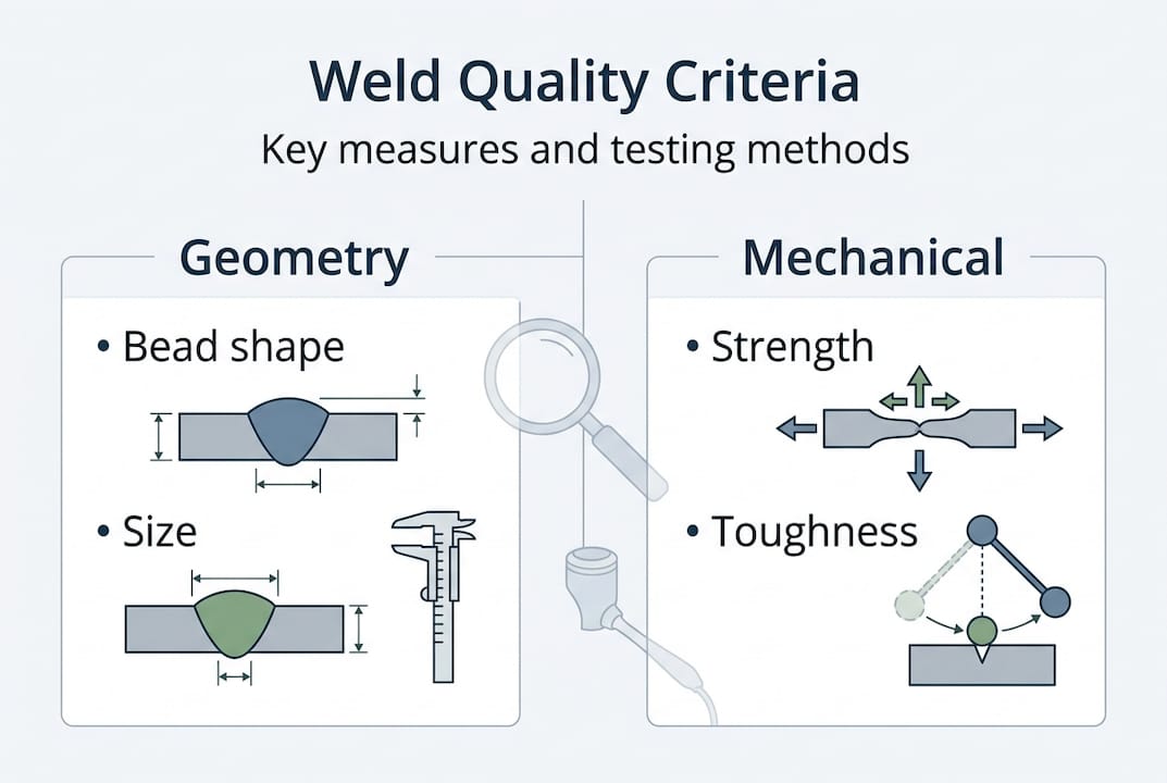
Weld quality is not a single number or a pass/fail checkbox. It’s a layered assessment that covers geometry, mechanical performance, and the integrity of the weld’s internal structure. Getting this right means understanding what each dimension measures and why it matters for your specific application.
Geometric criteria cover the visible and measurable shape of the weld. This includes bead width, reinforcement height, undercut depth, overlap, and root penetration. These are evaluated against tolerances defined in standards like ISO 5817, which classifies welds into three quality levels: D (moderate), C (intermediate), and B (stringent). Level B is required for fatigue-dominated applications, such as structural joints in bridges, pressure vessels, and automotive chassis components. Getting the geometry right is not just cosmetic. Flank angle, toe radius, and misalignment directly influence stress concentration and fatigue life.
Mechanical criteria go deeper. Tensile strength, yield strength, impact toughness, and hardness across the weld and heat-affected zone (HAZ) are all measured to confirm the joint can handle real-world loads. Hardness testing is especially critical in high-strength steels where the HAZ can become brittle if heat input is not controlled precisely.
Non-destructive testing (NDT) fills in what you can’t see or measure directly. Ultrasonic testing, radiographic inspection, magnetic particle testing, and dye penetrant inspection each target specific defect types: porosity, cracks, lack of fusion, and inclusions. For complex joints with residual stress concerns, computational welding mechanics (CWM) is increasingly used to model stress distribution and predict failure zones before testing even begins. CWM allows engineers to simulate the entire thermal cycle and predict residual stresses in areas that NDT cannot easily access.
| Quality dimension | Key metrics | Relevant standard |
|---|---|---|
| Geometric | Bead profile, toe radius, misalignment | ISO 5817, AWS D1.1 |
| Mechanical | Tensile strength, hardness, toughness | AWS D8.1, ASME IX |
| NDT/Internal | Porosity, cracks, fusion defects | ISO 17635, AWS B1.10 |
| Fatigue/Cyclic | Geometry quantiles, stress concentration | ISO 5817 Level B |
A few critical points worth noting for shop owners working across multiple industries:
- Fatigue-dominant applications always require stricter criteria than static load applications
- Automotive spot welds follow AWS D8.1 with specific nugget size minimums per material thickness
- Residual stress from welding can accelerate corrosion and cracking in service, even when visual and mechanical tests pass
- Weld quality standards are not universal. The standard you apply must match the application, material, and loading conditions
Understanding these dimensions is the foundation. Without it, you’re measuring the wrong things and passing welds that will fail in service.
Process parameters and material preparation: Essential ingredients
With clear quality criteria established, the next question is: what operational variables actually control those outcomes? The answer starts with your process parameters and how well you’ve prepared the base material before the arc ever strikes.
Current, voltage, and heat input are the core process variables. Heat input is calculated as (current x voltage x 60) divided by travel speed in mm/min, expressed in kJ/mm. Too low, and you risk lack of fusion, cold laps, and insufficient penetration. Too high, and you introduce excessive HAZ growth, distortion, and grain coarsening that weakens the joint. For advanced high-strength steels (AHSS), this window is tight. Process parameters including current, voltage, and heat input must be dialed in precisely for each material grade and joint configuration. There’s no universal setting that works across the board.
Travel speed is often underestimated. Slowing down doesn’t just increase heat input. It changes the bead shape, affects shielding gas coverage, and alters how the weld pool solidifies. Inconsistent travel speed, even by a few inches per minute, creates variation in bead geometry that shows up as fatigue scatter in testing.
Material preparation is where many shops lose quality before the weld even starts. Edge preparation method matters more than most operators realize. Oxy-fuel cutting creates a 2 to 3 mm HAZ along the cut edge with hardness values reaching 250 to 450 HV1, which significantly increases brittleness and reduces fatigue life. Clean milling produces a surface that is 6 to 10 times smoother (by Ra measurement) with no thermal damage. For fatigue-critical joints, milling is not optional. It’s the correct choice.
Coated materials add another layer of complexity. Zinc-coated steels are common in automotive and construction applications. The Zn coating reduces contact resistance at the faying surface, which means higher current is required to form an adequate nugget in resistance spot welding. The result is a larger nugget, but the process window narrows. Exceed the upper current limit and you get expulsion. Stay too low and you get an interface failure mode instead of the desired pullout failure. Both are quality failures with very different root causes.
Pro Tip: When switching from uncoated to Zn-coated AHSS, don’t just bump up current and assume you’re done. Requalify the full parameter set including electrode force and weld time. The coating changes the entire dynamic of nugget formation.
Joint design and fit-up also feed directly into fatigue performance. Misalignment, gap variation, and inconsistent root opening create stress concentrations that no amount of post-weld treatment can fully eliminate. Investing time in industrial welding tools and fixturing to hold tight tolerances before welding pays dividends in fatigue life and rework reduction.
Operator skill and contamination control: Human and environmental influences
Even with perfect parameters and prepared material, a poorly trained operator or a contaminated shielding environment will produce defective welds. These human and environmental factors are often the hardest to control consistently across a busy shop floor.
Welder skill and certification directly affect the consistency and repeatability of weld quality. A certified welder following a qualified welding procedure specification (WPS) produces predictable results. An uncertified operator working from memory introduces variation. Welder qualification and shielding gas control are consistently identified as primary drivers of weld quality outcomes across process types. AWS, ASME, and ISO all have certification frameworks that define what a welder must demonstrate before working on code-governed work. These aren’t bureaucratic hurdles. They’re evidence that the person running the torch understands what quality looks like and how to achieve it.
Consistency under fatigue is a real factor on long shifts. A welder who performs perfectly at the start of a shift may drift in travel speed, arc length, or torch angle as the day progresses. Shops that track this through periodic visual checks or weld monitoring systems catch drift before it becomes a rework problem.
“A qualified procedure without a qualified operator is a document, not a quality system. The human element is where standards become real or fail entirely.”
Shielding gas contamination is a silent quality killer. Moisture, oxygen, and nitrogen intrusion into the shielding gas envelope cause porosity, oxidation, and nitrogen embrittlement in the weld metal. Check gas hose connections regularly for micro-leaks. Purge the line before starting on critical joints. Store shielding gas cylinders properly and never use a cylinder that has been left open without a regulator attached.
Wire and filler metal quality matters just as much. Contaminated MIG wire, whether from moisture, oil, or surface oxidation, introduces hydrogen and other impurities directly into the weld pool. Hydrogen-induced cracking (also called cold cracking) is one of the most dangerous defect types because it can occur hours or days after welding, long after visual inspection has passed the joint. Using MIG wire with controlled chemistry and proper storage practices eliminates this risk.
PPE and arc environment also play a role. A welder squinting through a suboptimal lens shade is not going to maintain consistent arc length or torch angle. Proper burn protection and visibility through a high-quality helmet with accurate color rendering allows the operator to see the weld pool clearly and respond to changes in real time.
Pro Tip: Establish a contamination control checklist for your shop. Include wire storage conditions, gas hose inspection intervals, base metal cleaning requirements, and helmet lens inspection. Run it weekly, not just when problems appear.
Testing, benchmarks, and empirical standards: Proving quality
Mastering the inputs is necessary but not sufficient. You need a structured testing and validation approach to prove that your welds meet the required standard for each application. This is where empirical benchmarks and systematic testing come in.
Destructive testing remains the gold standard for qualifying welding procedures. Tensile tests, bend tests, macro sections, and impact tests all verify that the weld metal and HAZ perform as required under controlled loading. For resistance spot welding, peel tests and chisel tests are the standard shop-floor methods for confirming nugget formation and failure mode.
Empirical benchmarks from AWS D8.1 define minimum nugget size requirements for automotive spot welds based on material thickness. For QP980 steel, uncoated specimens reach peak tensile-shear loads of 28 kN while Zn-coated specimens peak at 24 kN. The critical current for achieving pullout failure mode is 9.5 kA for uncoated and 9.0 kA for coated material. These numbers matter because interface failure, where the nugget separates at the faying surface rather than pulling material out, is a quality failure even if the load value looks acceptable.
| Material | Coating | Peak tensile-shear | Critical current |
|---|---|---|---|
| QP980 steel | Uncoated | 28 kN | 9.5 kA |
| QP980 steel | Zn-coated | 24 kN | 9.0 kA |
| AHSS general | Varies | Per WPS | Per WPS |
Fatigue testing and geometry quantiles deserve special attention. Average weld geometry values don’t predict fatigue scatter well. Geometry quantiles, not means, best predict fatigue scatter in welded joints under cyclic loading. This means your quality system needs to track the worst-case geometry in a production batch, not just the average. A weld with an average toe radius that passes inspection can still contain individual toes that create severe stress concentrations.
Key testing methods every industrial shop should have in its quality program:
- Macro section examination for fusion, penetration, and HAZ width
- Vickers hardness traverses across the weld and HAZ
- Tensile and bend testing per the applicable WPS qualification standard
- NDT (UT or RT) for critical structural joints
- Peel and chisel tests for spot weld qualification
Using performance-grade MIG wire with certified chemistry and documented heat numbers makes traceability straightforward when a test result needs to be investigated.
The uncomfortable truth about weld quality standards
Here’s something most quality discussions avoid saying directly: meeting a standard does not guarantee a quality weld in service. Standards are minimum baselines, written to cover the broadest range of applications. They cannot anticipate every combination of material, geometry, loading, and environment your shop encounters.
We’ve seen shops that pass every audit, hold every certification, and still produce joints that fail in the field because their process drifted in ways the standard doesn’t measure. The standard said the weld was acceptable. The application said otherwise.
Real quality comes from continuous shop-floor feedback. It means tracking not just whether welds pass inspection but how they perform over time. It means adjusting parameters when material lots change, when ambient temperature drops, or when a new operator joins the line. Advanced weld quality discussions increasingly point toward digital monitoring and AI-assisted process control as tools for closing this gap. These technologies can flag parameter drift in real time, before a defective weld gets made. Quality control innovation using AI is moving from aerospace into general fabrication, and shops that adopt it early will have a measurable advantage.
Standards give you a floor. Your shop culture, your monitoring systems, and your willingness to act on data are what build the ceiling. Don’t confuse compliance with competence.
Shop smarter with Simpleweld tools and solutions
The factors covered in this article, from parameter control to material prep to operator skill, all depend on having the right equipment and consumables in place.
Whether you’re tightening your TIG process with a Lincoln Square Wave TIG 200 for consistent arc control, upgrading your filler metal selection with a premium welding rod that meets your mechanical property requirements, or sourcing a full range of welding and fabrication equipment for your shop, Simpleweld carries industrial-grade products built for professional performance. Browse the full catalog and find the tools that match your quality standards.
Frequently asked questions
What is the most reliable way to assess weld quality in industrial applications?
A combination of geometric inspection, mechanical testing, and non-destructive testing offers the most reliable assessment, with computational welding mechanics (CWM) added for complex joints where residual stress prediction is critical.
How do coated materials like zinc affect weld quality?
Zn-coated materials reduce contact resistance and require higher welding currents to form an adequate nugget, yielding larger nuggets but narrowing the acceptable process window and requiring careful parameter management to avoid expulsion or interface failure.
What standards define weld quality for automotive or fatigue-dominated applications?
AWS D8.1 and ISO 5817 Level B are the primary standards for automotive spot welds and fatigue-dominant structural applications, specifying minimum nugget sizes, failure modes, and geometry criteria that go well beyond basic visual acceptance.
How does material preparation influence weld quality?
Clean milling produces edges that are 6 to 10 times smoother than oxy-fuel cutting with no heat-affected zone hardening, which directly improves fatigue life and reduces the risk of HAZ cracking in high-strength steel applications.