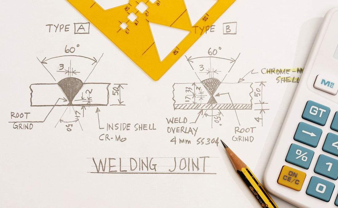
Understanding Welding Symbols
Welding blueprints are complex but, with enough preparatory education, digestible. They require specialized knowledge from seasoned professionals to understand and actualize. If you’re reading this article, that’s probably you. However, if you’re not and are doing a home improvement project, for example, we provide you with all the tools to read welding blueprints effectively.
Let’s first ask the question: Why is it essential to understand welding blueprints? Well, the answer is pretty simple: it will help your metal fabrication work better and more efficiently in shorter amounts of time. The bad news is that many welders don’t know how to read their blueprints properly. The good news is that we can help; this article will show you how.
The next question to answer is, what is a welding symbol? Well, let’s identify their function first. A welding symbol is a symbol on the blueprint at specific areas that specify how you will carry out a particular type of work on your welding project.
Let’s now dive into the different symbols, their indications, and their functions.
The standard blueprint symbol is a line with an arrow pointing in different directions. It may sound simple, but this welding symbol can be manipulated in multiple ways to tell the welder various things.
Every line’s arrow will point in the direction of the weld. The line itself is called the leader line or reference line. In terms of direction, the arrow can point either downward or upward.
It’s also important for the welder to recognize the tail ends of the leader or reference lines. Here’s where it starts to get complex. Those tail ends can have multiple forks that go off in different directions. The tail signifies specific instructions regarding the weld and weld direction.
Then, you add geometric shapes or symbols around the center of the reference line. Finally, you have words underneath or on top of the central-area symbol that denote the type of weld to be performed. These include such terms as “fillet weld,” “bevel,” “j-groove weld,” and others.
Sometimes the symbols look a little like hieroglyphics, so familiarize yourself with them, or both, if you want an additional educational adventure!

Identifying Weld Types and Joints
There are over a dozen types of welds you can perform.
- Fillet weld
- Plug weld/slot weld
- Spot weld/projection
- Back/backing
- Seam weld
- Melt-thru
- Surfacing
- Flange
- Corner
- Edge
- Square
- Bevel
- V
- U
- J
- Flare-V
- Flare-bevel
- Weld all-around
- Flag-toward-tail/field weld
- Flush
- Convex
- Concave
Different letters signify specific instructions for the welding process. They are:
- A. Angle of countersink
- Chipping finish
- Finish symbol
- Grinding symbol
- Weld length
- Machining finish
- Number of projection or spot welds
- Pitch of welds
- Root opening
- Depth of preparation, size of strength
- Specification process
Regarding joint specifications, the reference/leader line serves as the weld joint. If a symbol and words are put above the line, they’re above the weld joint; the same goes for doing so beneath the line.
Dimensions
Dimension is also indicated in welding symbols. Dimensions are written instructionally above or below the weld line. They will be used for the joint on the arrow side if they're written underneath. If they’re over the line, they apply to the joint on the opposite side.
So why are dimensions important in a welding blueprint? Generally speaking, they make the blueprint drawing easier to read. Each dimension is indicated in both words and numbers—the words we discussed above. The numbers refer to angles, root openings, or dimensions.
Bill of Materials
The bill of materials is a pretty nifty section of the blueprint. Essentially, it’s a list of all the materials you’ll need to complete the job. The bill of materials is meticulously detailed, and for a good reason – it includes specifications, quantities, and sizes.
Common Blueprint Types
Next, we want to review a prominent section that details the different types of weld blueprints.
According to the Universal Technical Institute, the different welding blueprint forms include:
- Isometric
- Orthographic
- 3D
This video does a great job explaining everything you need to know about the basics of weld blueprints, including examples of the different kinds.
Frequently Asked Questions
What are the three main types of weld blueprints?
They are isometric, orthographic, and 3D.
Where are weld dimensions notated?
They are notated either above the reference line or below it.
What is the bill of materials on a weld blueprint?
This is a super-detailed section of the blueprint that indicates all of the materials and equipment you’ll need for your particular welding job.

Conclusion
This article covered a great deal of information about how to read weld blueprints.
We reviewed symbols and their importance, including all 20 different ones. We also discussed the basic structure of a weld symbol, which is a line (called the reference or leader line) with an arrow pointing upwards or downwards.
We recognized how many variations this line could have given forks, symbols, numbers, and words, all above or below the leader line.
There was also information about the blueprint drawing itself, including an instructional video and a definition/description of the Bill of Materials for weld blueprints.
Overall, weld blueprints are pretty complex and need proper education to understand – and, more importantly – apply them properly. This article aims to provide the foundational knowledge to do just that.
Ecenrode Welds has all the welding products you could need available online. Get that next welding project started right away – blueprint included!

