

Structural welding is not a generic skill you can swap in from any welding job. It governs the integrity of bridges, high-rise frames, industrial platforms, and every critical load-bearing assembly in between. Every joint must conform to coded procedures, qualified welders, and documented inspections, because a failure here is not just a rework cost. It is a public safety event. This guide breaks down the definitions, core techniques, standards, inspection requirements, and quality preparation strategies that contractors and industrial professionals need to stay compliant and deliver work that actually holds up.
Table of Contents
- What structural welding is and why it matters
- Core structural welding techniques: Fillet vs. groove welds
- Standards, qualifications, and inspections for compliance
- What most pros overlook: Quality factors and preparation for structural welds
- The uncomfortable truth: Compliance is not enough—why true pros obsess over quality
- Get the right tools and resources for structural welding success
- Frequently asked questions
Key Takeaways
| Point | Details |
|---|---|
| Structural welding defined | It involves joining key load-bearing components using regulated processes for safety and compliance. |
| Fillet vs. groove welds | Fillet welds offer 60–70 ksi strength, while groove welds can exceed 80 ksi for high-stress joints. |
| Code compliance vital | Following qualification and inspection standards protects against structural failure and legal issues. |
| Edge prep matters | Milling creates smoother, safer joints than oxy-fuel and helps prevent defects in thick steel. |
| Quality goes beyond compliance | True professionals focus on continuous improvement, not just code passing, for durable, safe projects. |
What structural welding is and why it matters
Structural welding is the process of joining load-bearing components such as beams, columns, girders, and trusses using controlled welding procedures that meet legally enforceable codes. This is not the same as welding a gate hinge or a decorative railing. The distinction matters because the consequences of failure are categorically different.
When a structural weld fails, the entire load path it supports can collapse. That makes every decision in the process, from material selection and joint design to preheat temperature and post-weld inspection, a safety-critical action. Contractors working on commercial buildings, bridges, or industrial facilities operate under an entirely different layer of legal and technical obligation compared to shops doing ornamental work.
Here is what separates structural welding from general fabrication work:
- Welding Procedure Specifications (WPS) must be written, tested, and approved before production welding begins
- Procedure Qualification Records (PQR) document the test results that validate each WPS
- Welder Performance Qualifications (WPQ) confirm each individual welder can execute the approved procedure
- Preheat and interpass temperature controls are mandatory for specific base metals and thicknesses
- Non-destructive testing (NDT) must be performed using accepted methods at defined frequencies
The UFGS 05 05 23.16 structural welding standard requires qualified welders and procedures, with NDT covering visual, ultrasonic, radiographic, magnetic particle, and liquid penetrant testing. Inspection percentages range from 10% for lower criticality welds up to 100% for the most safety-critical connections. Acceptance criteria are tied directly to the stress category of the joint.
“A structural weld is not just a weld. It is a documented, inspected, and code-backed engineering decision. Treating it as anything less is where projects get into serious trouble.”
The reliability of welding equipment for industrial use plays directly into whether your welders can execute those procedures consistently. Equipment that drifts in amperage or voltage output will produce welds that look acceptable to the eye but fail under ultrasonic testing. Understanding weld quality standards from the start keeps the team aligned on what success actually looks like before the arc is struck.
Now that you know how structural welding stands apart from general welding, let’s break down the key methods used to achieve reliable structural joints.
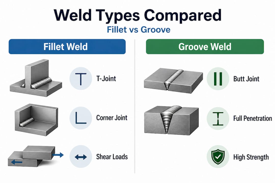
Core structural welding techniques: Fillet vs. groove welds
The two dominant weld types in structural work are fillet welds and groove welds. Choosing the right one is not purely a preference. It affects structural performance, inspection requirements, cost, and code compliance. Confusing the two, or using fillet welds where full penetration groove welds are required, is one of the most common and costly errors on structural projects.
| Feature | Fillet weld | Groove weld |
|---|---|---|
| Joint geometry | Triangular cross-section at a corner or T-joint | Fills a prepared groove between two base metals |
| Typical shear strength | 60 to 70 ksi | Exceeds 80 ksi (full penetration) |
| Best application | Lap joints, T-joints, secondary connections | Butt joints, primary moment connections |
| Inspection demand | Visual plus surface NDT common | Full volumetric NDT often required |
| Cost | Lower material and prep cost | Higher due to joint preparation |
Fillet welds are the workhorses of structural fabrication. They join two pieces at a right angle without requiring the elaborate joint preparation that groove welds demand. The minimum fillet size is determined by the thicker of the two base metals being joined. For a 1/4 inch plate, the minimum fillet size is 3/16 inch. The maximum edge fillet is limited to the plate thickness minus 1/16 inch, preventing overwelding that actually weakens the joint through distortion and residual stress.
Groove welds come into play when full penetration is required. Full penetration groove welds develop weld strength exceeding 80 ksi, effectively matching or exceeding the base metal strength. Partial joint penetration groove welds sit between fillet and full penetration in both strength and cost. They are used frequently in compression members and secondary moment connections where full penetration is not required by design.
One critical insight that many contractors learn the hard way: simulation and real-world testing both show that increasing weld size 25 to 50% above the design minimum for high-load connections significantly reduces the probability of fatigue-driven failure in dynamic loading scenarios. This matters on crane runways, platforms subject to vibration, and bridge connections.
Pro Tip: For connections carrying significant cyclic or dynamic loads, such as industrial platforms near rotating equipment or vehicle bridges, consider specifying fillet and groove weld combinations rather than relying on a single joint type. Cross-referencing your fillet and groove weld benchmarks against the actual design loads before fabrication prevents costly repair cycles after inspection.
Weld size selection also directly affects project cost. Oversizing welds wastes wire, increases heat input, raises distortion risk, and slows production. Undersizing fails inspection and requires grinding and rewelding, which costs significantly more than getting it right the first time. A well-calibrated team checks weld size with gauges at every shift, not just during the final QC pass.
With essential techniques clarified, compliance with standards and certifications is the critical next step for every professional.
Standards, qualifications, and inspections for compliance
AWS D1.1 is the governing structural welding code in the United States for steel structures. It sets the framework for procedure qualification, welder qualification, production welding controls, and inspection requirements. Most project specifications reference AWS D1.1 directly, and deviations from it require documented engineering approval. Other codes, such as AWS D1.5 for highway bridges or AISC certification requirements, layer additional requirements on top.
Here is the standard sequence for getting a project’s welding operations into compliance:
- Identify applicable codes from contract documents and structural drawings
- Develop or obtain pre-qualified WPS documents that match the base metals, filler metals, and joint configurations in scope
- Conduct procedure qualification testing (PQR) if non-prequalified joints are used, documenting all essential variables
- Qualify welders through WPQ testing using the appropriate position, process, and base metal combination
- Establish preheat and interpass controls based on material specifications and joint thickness
- Implement inspection hold points in the production schedule, aligned with NDT requirements
The five primary inspection methods used in structural welding are visual testing (VT), ultrasonic testing (UT), radiographic testing (RT), magnetic particle testing (MT), and liquid penetrant testing (PT). Each targets different defect types and joint configurations.
| Inspection method | Defects detected | Typical use case |
|---|---|---|
| Visual (VT) | Surface cracks, porosity, profile issues | All welds, always first |
| Ultrasonic (UT) | Internal flaws, lack of fusion, cracks | Groove welds, heavy plate |
| Radiographic (RT) | Internal voids, inclusions, cracks | Full penetration groove welds |
| Magnetic particle (MT) | Surface and near-surface cracks | Ferromagnetic materials |
| Liquid penetrant (PT) | Surface-breaking cracks | Non-magnetic materials |
Per the UFGS structural welding standards, inspection frequency is not uniform. Stress category and joint criticality determine whether 10%, 25%, or 100% of welds receive volumetric inspection. Cyclically loaded or tension-dominant joints get the highest scrutiny.
Proper preparing weld joints before production is a prerequisite for passing any of these inspections. A joint that is poorly fitted, contaminated, or inconsistently beveled will produce internal discontinuities that no amount of post-weld repair can fully fix without significant cost. Contractors who want to sit for AWS D1.1 qualification can use a welder certification test plate specifically configured for limited thickness qualification under that code.
Pro Tip: Build a compliance binder for every project that contains all WPS, PQR, WPQ, material certifications, preheat logs, and inspection reports in one accessible location. Auditors and third-party inspectors will ask for these on-site, and scrambling to assemble them from scattered records is a red flag. You can support your team’s preparation with welding training resources that cover qualification procedures and code requirements in practical terms.
Compliance is only part of the story. Achieving high-quality, durable welds requires an understanding of the latest quality and preparation strategies.
What most pros overlook: Quality factors and preparation for structural welds
Even experienced structural welders sometimes underestimate how much surface preparation affects the final weld. The assumption is that once you have the right procedure and qualified personnel, the weld will pass. That assumption breaks down in thick, high-strength steels where edge condition has a direct impact on heat-affected zone behavior and defect rates.
Research on edge milling versus oxy-fuel cutting in structural steel work reveals specific performance differences that matter on real projects:
“Milling edges reduces surface roughness 6 to 10 times compared to oxy-fuel cutting, avoids heat-affected zone hardening between 250 and 450 HV1, and does so at a comparable cost of approximately 2 EUR per meter. This difference is critical for weld quality in thick S355J2N structural steel.”
That hardness band in oxy-fuel cut edges is not just a quality concern. It is a hydrogen cracking risk. When you weld into an edge that has been hardened by the thermal cutting process, you are setting up conditions for delayed cold cracking, particularly in the root pass of heavy section groove welds. Inspection may pass initially, but failure can develop days later as hydrogen diffuses through the heat-affected zone.
Here are the preparation practices that separate top-performing structural fabrication teams from those who fight rework cycles:
- Grind or mill thermally cut edges on plates thicker than 1 inch before fitting to remove the heat-affected zone
- Clean joint faces to bright metal within 2 inches of the weld zone, removing mill scale, rust, paint, moisture, and any cutting fluids
- Verify fit-up with gauges before tacking, keeping root openings within WPS tolerances, not just within visual acceptance
- Check bevel angles with a protractor or bevel gauge rather than estimating by eye
- Stage preheat properly using temperature-indicating crayons or contact thermometers, not by guessing from color
- Monitor interpass temperatures with the same rigor as preheat, since overheating between passes degrades toughness in structural steels
The MIG welding process is widely used in structural shops for its productivity advantages, but the wire feed consistency and shielding gas coverage must be tightly controlled. Any porosity introduced through contamination, drafts, or inadequate gas coverage creates reject conditions under UT or RT.
Selecting the right cutting tools for fabrication affects both the quality of the prepared edge and the efficiency of your shop floor. Plasma cutters with controlled kerf and minimal dross, paired with proper grinding wheels, get edges to the right condition faster and more consistently than older oxy-fuel methods on production runs. If your shop is still defaulting to oxy-fuel on structural plate, running a direct comparison on edge condition and downstream NDT results will make the cost case for upgrading obvious.
Investing in proper strong weld joint prep practices upstream eliminates the vast majority of weld discontinuities before the arc is ever struck. It is always cheaper to prevent a defect than to find and repair it after inspection.
With quality assurance in mind, it is time to step back and see how these aspects fit into the bigger picture of project success.
The uncomfortable truth: Compliance is not enough—why true pros obsess over quality
Here is the reality that the codes do not say out loud: a weld can pass every inspection requirement, carry the right stamps, and still perform poorly in service. Code compliance is the floor, not the ceiling. The acceptance criteria in AWS D1.1 define the minimum quality threshold for a weld to be legally accepted on a project. They do not guarantee optimal performance over a 50-year service life under dynamic loads, aggressive environments, and the kind of stress concentrations that real structures develop as they age.
We have seen this play out on industrial maintenance projects where welds compliant at installation showed fatigue cracking within three years because the fabrication team treated the inspection report as the finish line rather than the starting point. Every discontinuity that falls just inside the acceptance threshold is still a discontinuity. It still reduces the weld’s effective cross-section. It still acts as a stress riser under cyclic loading. Passing inspection does not make it invisible to physics.
The welders and fabricators who consistently deliver structures with 20-plus-year maintenance-free service lives are the ones who treat the quality standard as a baseline and hold themselves to a higher internal standard. They reject welds that technically pass but look wrong. They re-examine fit-up that was closed out in the morning when the temperature was different by afternoon. They track their own defect rates by welder, by joint type, and by shift, and use that data to drive team-wide improvement. You can sharpen those instincts with in-depth weld quality tips that go beyond what the code manual explains.
Pro Tip: Implement a monthly peer review session where your structural welding team examines a sample of completed welds together, both passed and failed, and discusses what drove the outcome. Teams that normalize this practice reduce their field repair rates significantly within six months. The combination of documentation discipline and craftsmanship culture is what separates top structural contractors from those who are always chasing the next repair cycle.
Continuous improvement in structural welding is not a soft concept. It is a business and safety imperative that shows up directly in your project close-out costs, client retention, and your ability to win contracts that require demonstrated quality track records.
Get the right tools and resources for structural welding success
Structural welding demands precision at every step, from the equipment your team uses to the consumables that go into every joint. Cutting corners on tools or skipping qualification support is exactly where projects start accumulating hidden costs.

At Simpleweld.com, we stock everything structural welding professionals need to stay compliant and perform at the highest level. Browse our selection of industrial-grade structural welding machines built for the heat inputs and duty cycles that structural fabrication demands. Pair your machine with the right approved welding rods matched to your base metal and WPS requirements. And if you or your team need to sit for qualifications or refresh your code knowledge, our professional welding certifications resources give you a clear path forward. We supply the tools. You deliver the quality.
Frequently asked questions
What is the difference between structural welding and other types of welding?
Structural welding involves joints that support significant loads and must comply with strict codes and documented inspections, unlike ornamental or non-structural welding where qualified procedures and NDT are not legally required.
How strong are typical structural welds?
Fillet welds carry a shear strength of 60 to 70 ksi, while full penetration groove welds exceed 80 ksi, effectively matching the strength of the base metal in most structural steel grades.
Which inspection methods are common in structural welding?
Structural welding inspections use five NDT methods: visual testing, ultrasonic testing, radiographic testing, magnetic particle testing, and liquid penetrant testing, selected based on joint type and criticality.
Does edge preparation affect weld quality?
Yes. Milling edges delivers 6 to 10 times lower surface roughness than oxy-fuel cutting and eliminates heat-affected zone hardening, which directly reduces the risk of hydrogen cracking in thick structural steel joints.